I took general engineering course called, “Engineer Your World” when I was grade 9. This is a course given by my high school and it is developed by the collaboration of NASA (The National Aeronautics and Space Administration) & The University of Texas at Austin. During this course, I learned about what is engineering and how it impacts society. Through over different projects I came up design solutions to complex challenges using a process. I had been one of the youngest student in the class. At beginning, I felt that I may not able to catch up with higher graders but I took it as a challenge and I tried to enjoy learning instead of having frustration. This project was a team effort and I had really fun working with my classmates and having lots of brainstorming to complete an engineering report to management of an apartment building. Enjoy reading engineering report that we came up with my classmates to modify the design of an apartment building for increased safety during any possible earthquake and improved capacity.
Part I: Summary and Recommendation
Families live in an apartment building in a rapidly developing part of a populous town in northeast India. Our client, the owner of the building, wants to make more money by expanding his property and renting out to more families. The local government encourages this, to help deal with the influx of people into the city. At the same time, the locals are worried about earthquakes, since the city is around a fault block. Because of new laws, the owner must make sure if any building that goes on his land will resist an earthquake and keep residents inside safe.
We have tested and evaluated models of the existing building on a small scale. Based on our results, the original design proposed by the owner is not safe. The original building also may not be safe during seasons of heavy snowfall.
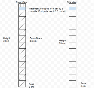
Based on further investigations, we recommend an alternative design to allow more capacity and increase safety. We propose a new building that is 97.5 m tall on the same footprint as the original building (Figure 1, drawing 125x smaller than actual size). It is designed to withstand the forces of a typical earthquake in the region by India.
Testing shows that during an expected earthquake, this new design will have an 18% decrease in peak accelerations compared to the original building design and a 31% decrease in peak accelerations compared to the original design proposed by the owner. Its resonant frequency lies outside the typical shaking frequency of earthquakes in the region, which increases safety.
Construction costs are estimated to be $696,900. These costs fall within the budget proposed by the client.
Part II: Information Supporting the Recommendation
The test system and the modeling process is described with the following workflow. The photo of the test system shown in Figure2.
The workflow for the testing is with the following steps
- Clamp shaker table in place and connect all the electronics
- Fix building to shaker by using binder clips on the core base
- Distribute the load evenly onto each level. Use two washers and one binder clip per level
- Attach the roof load, filled with 150 g of weight
- Attach the accelerometer to the roof and attach one to the base for reference data
- Use LabVIEW software to shake the building and collect accelerometer data
- Measure data in excel
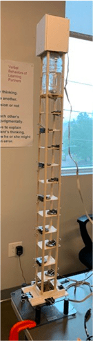
Figure 2: Picture of model
Accelerometers are sensors which measure acceleration. Acceleration is a measure of how quickly speed changes with time. The measure of acceleration is expressed in units of g-scale (G). The magnitude of acceleration changes from zero to a maximum during each cycle of vibration. It increases as the vibrating object moves further from its normal stationary position. Accelerometer-measured the data in two points, at roof and base. The base output is called A-output and the roof output is called B-output. Acceleration plotted over time for both outputs. The following plots show the results of different motor powers.

Figure 3: 5% of motor power- Acceleration (G) vs Time (s) plot
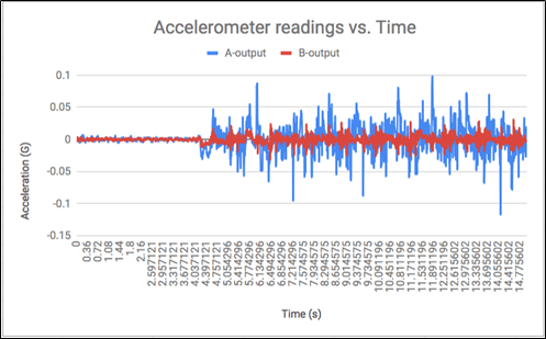
Figure 4: 10% of motor power- Acceleration (G) vs Time (s) plot

Figure 5: 15% of motor power- Acceleration (G) vs Time (s) plot

Figure 6: 20% of motor power- Acceleration (G) vs Time (s) plot

Figure 7: 25% of motor power- Acceleration (G) vs Time (s) plot

Figure 8: 30% of motor power- Acceleration (G) vs Time (s) plot

Figure 9: 35% of motor power- Acceleration (G) vs Time (s) plot
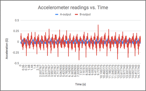
Figure 10: 40% of motor power- Acceleration (G) vs Time (s) plot
The figure below shows acceleration vs frequency plot.

The data shows that our building has a resonant period at 15% power. The data also shows the effectiveness of our building`s design due to the lowered acceleration. The client must understand that peak acceleration refers to how far the building moves and frequency refers to how fast the building moves. We can use this data to adjust the baffle system to counter the effects.
Tuned liquid damping design is recommended. Water tank balances building during earthquakes. Tuned liquid damping is water confined in a container, usually placed on top of a building that uses the sloshing energy of the water reduce the dynamic response of the system when it is subjected to excitation. It relies on a heavy liquid mounted to the top of a building and connected to viscous dampers that act as shock absorbers. When the building begins to oscillate, the liquid moves in the opposite direction, which reduces the amplitude of mechanical vibrations.
Earthquakes often knock buildings from their foundations. There are different solutions. One solution involves tying the foundation to the building so the whole structure moves as a unit.
Another solution is known as base isolation which involves floating a building above its foundation on a system of bearings, springs or padded cylinders. The lead core makes the bearing stiff and strong in the vertical direction, while the rubber and steel bands make the bearing flexible in the horizontal direction. Bearings attach to the building and foundation via steel plates and then, when an earthquake hits, allow the foundation to move without moving the structure above it. As a result, the building’s horizontal acceleration is reduced and suffers far less deformation and damage. Even with a base-isolation system in place, a building still receives a certain amount of vibrational energy during an earthquake. In increasingly more earthquake-resistant buildings, designers are installing damping systems. That is the reason, tuned liquid damping is considered for this project. Following study, Taipei 101 in Taiwan. Taipei 101 uses a tuned mass damper instead of tuned liquid damping. The two systems work in very similar ways, one uses the movement of liquid while the other is more complicated and moves a large mass in a liquid like movement.
Case Study: Taipei 101 in Taiwan
Taipei 101 stood as the world’s tallest skyscraper until the Burj Dubai opened its doors in 2010. And yet the massive, 1667-foot (508-meter) tower still represents a marvel of design innovation. One of its most impressive features is a 730-ton (662-metric-ton) active liquid damper that resides at the top of the building, between the 88th and 92nd floors. The huge sphere sits in a cradle formed by eight steel cables and connects to eight viscous dampers. If the building begins to sway, the damper counteracts the motion, reducing vibrations that could make inhabitants uncomfortable and could cause stress on the structure.

Figure 11: Top floor view of Taipei 101 in Taiwan
Our requirements were to withstand an earthquake and receive as minimum as possible. We also created stronger beams. Our design requirements were met in all ways.
| Given constraints | New design specs |
| Height Limit Max:120 m and Min:90 m | 97 m |
| Max Budget: $700,000 | $696,900 |
| Width 7.5 by 7.5 | 7.5 by 7.5 |
| Min floors: 12 | 14 |
Part III: Further Recommendations
Discussion to be provided as follows:
- The strengths and weaknesses of the recommended design and the evidence is there that it is a strength or weakness.
- Our design weaknesses include the added weight from the damping system as well as the required coding to allow the damping system to maximize its earthquake-resistant capabilities. Another weakness is the extra height required for the system. The strengths include added wind protection, great earthquake resistance, and efficient and simple design. Our design greatly reduced the acceleration at the top of the building. The design is also simple to maintain due to the easy ability to fix components. Although if the water tank sustained damage, there would be a slightly larger problem.
- Suggestions the weaknesses be accommodated or improved in the future.
- The weaknesses could be accommodated by using a more simple system and the addition of new materials to help reduce the risks formed with a larger heavier building.
- The validation of the performance of your design.
- We can validate the performance of our design through testing of more realistic models, the true performance of our design is not shown thoroughly in our basic model. A better model would include a more advanced system using baffle systems to accommodate the different shakes during an earthquake.
- The limitations of this design process and the factors were not considered in this study.
- The limitations include the width of the building as it limits the effectiveness of the damper. Factors that were not considered during this study included the strength and structural integrity of the real life building materials, and the design of the baffle system. A system that would move the water to best counter the shaking of the earth.
In conclusion, our design worked very well. With more time and experimentation we could improve our design greatly. Also implementing a baffle system would significantly aid in improving our design at all power percentages.
